Update 6/25/2023:
Update 3/17/2023:
I have been experimenting with constructing a synthesizer that uses mostly CMOS components that all work on single +5V power supply. Doing this solves a lot of system implementation, power supply, signal integrity, and PCB layout problems. For example, I am aiming to actually power the system with a standard power brick, such as the very common +12V type used for USB disk drives. This becomes possible due to the low power requirements for the system.
I have since decided that ±15V dual supply power also has advantages for analog waveform generation and signal processing has several advantages. Among them the ability to set reference voltages, plus symmetrical and asymmetrical voltages. In addition, both unipolar and bipolar options are available, which is handy for unipolar waveform generators for envelopes. And designs using dual voltages are also among my 20+ years of research and development on electronic music circuit designs.
The +5V circuits do work well, but I have since decided that +15V single supply power for analog waveform generation and signal processing has several advantages. Among them are 20+ years of research and development on LM3900 circuit designs.
I have been experimenting with constructing a synthesizer that uses mostly CMOS components that all work on single +5V power supply. Doing this solves a lot of system implementation, power supply, signal integrity, and PCB layout problems. For example, I am aiming to actually power the system with a standard power brick, such as the very common +12V type used for USB disk drives. This becomes possible due to the low power requirements for the system.
One aspect in applying single supply CMOS op amps is the need for a pseudo-ground, which is nominally Vdd/2. This is something I'm very familiar with already from my synthesizer design research with the LM3900 current-differencing op amp. In that research, bipolar signal processing is done with only a +15V single power supply. For this I created the concept of Voltage Zero Reference or VZR. This is programmed voltage that is intended to represent "0" in the circuit design. With the LM3900, any number of VZRs could be used in various local LM3900 circuits. These could all be used interoperably in a broader system, if the relative values of the VZRs were respected, or AC coupling is otherwise used. With CMOS op amps, and a lower power supply voltage (5V vs. 15V), it may be more providential to use a single VZR more widely. More particularly for circuits that need excellent DC accuracy there are both design and implementation advantages with single-supply voltage-mode op amps if the VZR is set with a precise reference voltage relative to ground.
One of the first things I wanted to tackle was a VCO implementation, blending together something new out of various other circuit designs tested over the years. I've tested various toplogies, but a lower power supply voltage creates issues as there is less voltage compliance available to circuitry. For example, with a bipolar voltage-controlled current source, approximately 2Vbe are needed, and that's a fairly good fraction out of +5V. With CMOS realization, it's obviously tempting to use CMOS switches to control currents or voltages, but I have also found multiple times that these devices are quite likely to have frequency-dependent capacitive charge injection into op amp integrators typically used in VCOs.
With such constraints as lower power supply voltage, I decided to look at the Howland Current Source, which is an op amp circuit that uses both positive and negative feedback simultaneously. The Howland circuit is capable of bipolar current generation. It only requires resistors, though they should be precision types. This type of circuit allows positive and negative current from a voltage differential about the VZR. Also, for this circuit I was testing precision rail-to-rail CMOS op amps, the Microchip Technology MCP6024. This is a quad low-power precision CMOS 10 MHz op amp which has ±250μV offset voltage. It has other good specifications too, like very low input bias current, large open loop gain, fast slew rate. The device is relatively inexpensive and available in distribution.
The test circuit design is shown in my engineering notes, below. U1A is the Howland circuit, and uses 4x 10KΩ 0.1% resistors. It accepts a test input Vi from my 14-bit Siglent function generator. This input would be square waves with a +2.5000V DC offset. U1B is a standard op amp integrator, which outputs ramp waveforms as Vo. The local VZR of nominally +2.5V is provided by U1D, which buffers a precision 1% resistor divider driven by +5V. U1C is powered off.
Following the engineering notes are various scope fotos of the circuit in action. One thing became clear only after running the tests. The directional current change from the Howland circuit depends on the VZR. As I had set that using a divider from Vdd (a typical practice for single supply op amps), the nominal center voltage is subject to both the actual Vdd voltage, as well as tolerance of the 1% resistors in the divider. An artifact of this situation is that +2.5000V from my 14-bit Siglent function generator is much more accurate than the VZR obtained from the divider. So, the whole circuit had an built-in offset voltage, which was driven by Vdd/2 ≠ 2.5000V. This shows up in uneven ramp generation by the integrator: for a common ΔV about 2.5000V, it was not common about VZR, but in fact slightly skewed. So the integrator responded accurately to this small imbalance. In future development with these types of designs, VZR will be created using a LM4040AIZ-2.5 0.1% precision reference, and all DC circuits will use that reference voltage integrally.


Test Circuit with MCP6204 Quad CMOS Op Amp

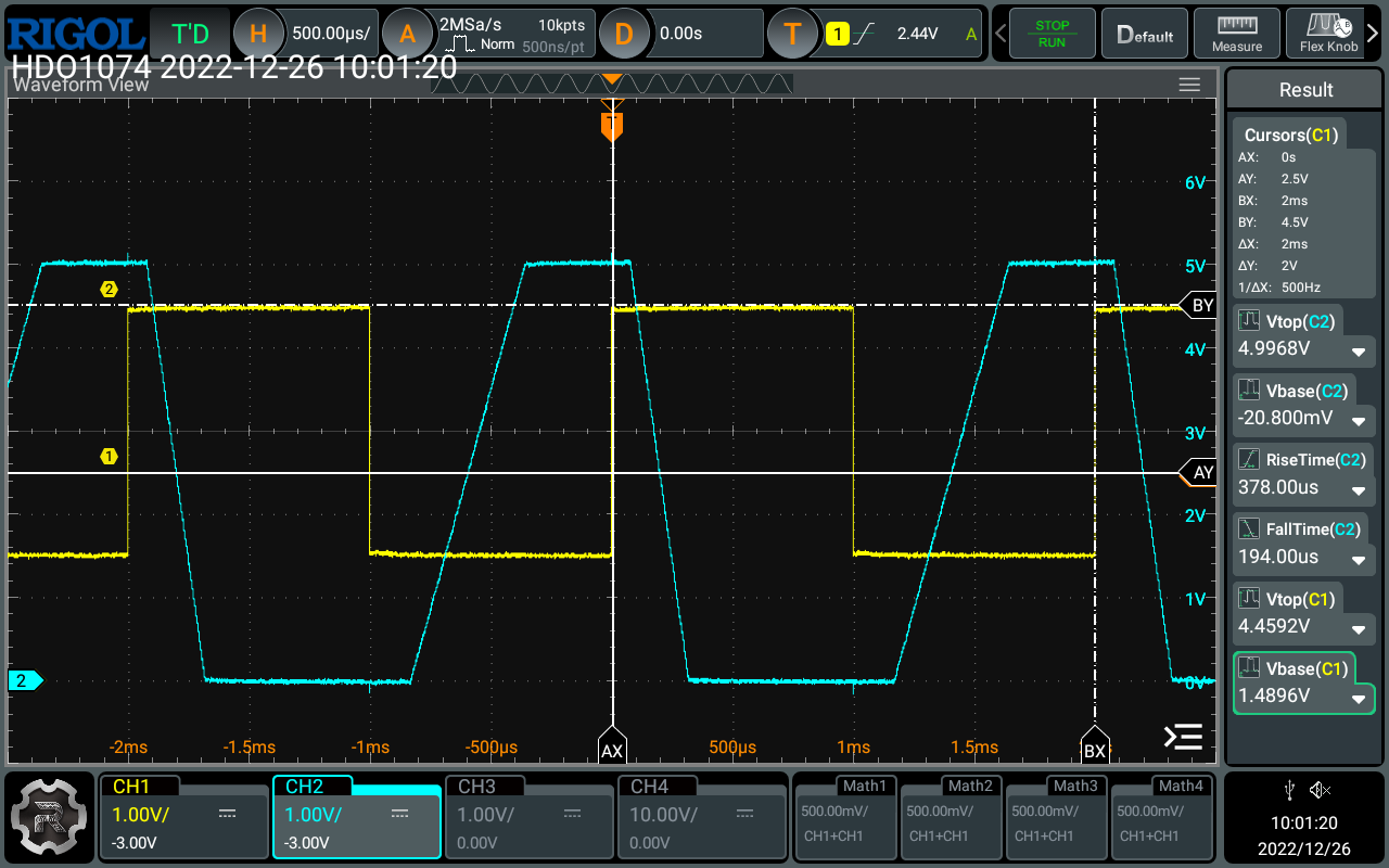
Stimulus of 2.5V ±1V, at 500 Hz, resulting in nearly equal ramps.

Testing 2.5V ±1V, at 250 Hz, and turning on slope measurement with the scope. Slight imbalance.
Changing the slope ratio 2:1.

The inverse, 1:2.

A more extreme test of 3:1 proportion in slope.

Slowing the ramps down with 2.5V ± 250mV stimulus. More asymmetry.

Even slower ramps from 2.5V ± 100mV stimulus. Wider disparity.

Quite apparent rate disparity from 2.5 ± 50mV input control. The slopes should be very close to the same, but the offset voltage error from Vdd/2 versus 2.5000V is a larger fraction of the control voltage.
Comments
Post a Comment