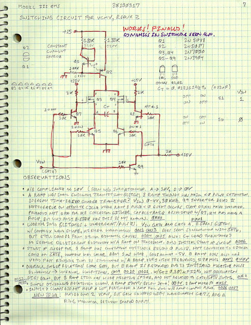
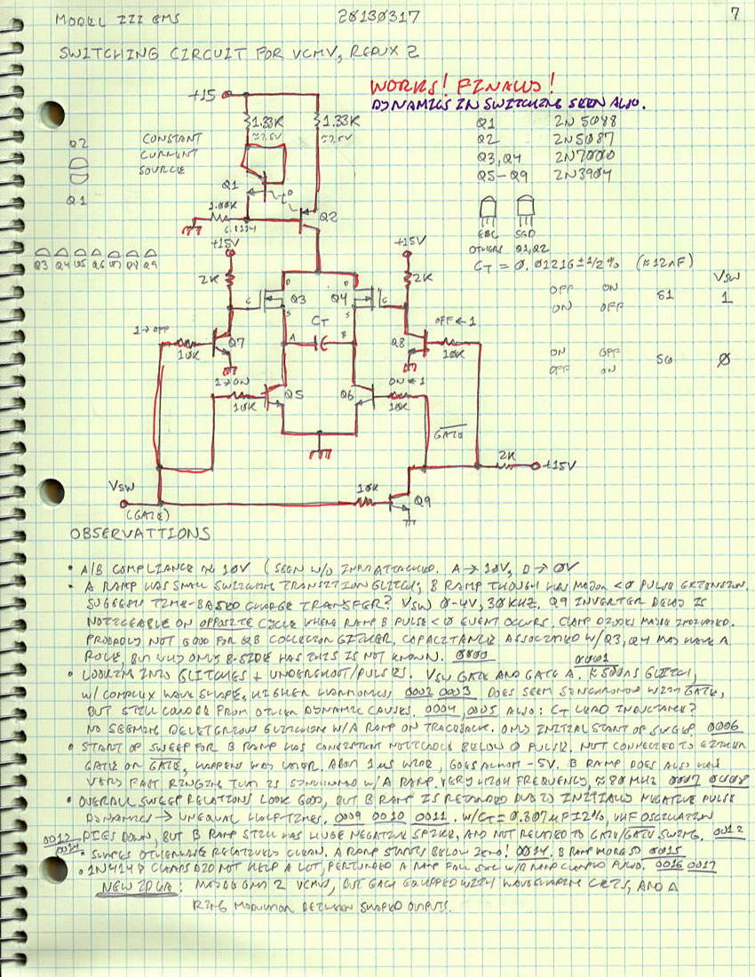
After several weeks of trying out switching circuits for a VCMV, finally one works. The key ingredient was to use a 2N7000 N-channel MOSFET as part of the switch network. The design switches currents from (what will be a voltage-controlled) current source to alternately charge a capacitor from both terminals, one then the other. For the present circuit, the topology chosen was to charge the capacitor up against ground. This is instead of charging it down from a switched precision reference voltage, which was done in earlier test circuits. Note that for over-all linearity and precision, this circuit design differs from a classical multivibrator in that there is only one capacitor instead of the usual two in the frequency determination network. This is made possible by current switching, with the idea being that one current source used two ways (for each half-cycle) should offer more timing stability and precision than the case where either two currents are used, or two different capacitors are used. Switching one current in two ways to one capacitor is a more precise way to create a timing interval than charging two different capacitors (which would have to be precisely matched), subject to the limitations that the switching circuits offer very little error. Getting this to work well with BJTs was a problem, so using a MOSFET with RDS < 5Ω seemed like it would work much better.
The circuit actually does generate half-period sawtooth waveforms, one for each half of a square-wave cycle. But the circuit has some interesting switching dynamics that affect the waveform fidelity and timing period. This is most likely a result from the 2N7000 which is highly capacitive. Nonetheless, there was still an anomaly, where one cycle charges quite differently than the other. Why is presently a mystery, though there are some plausible theories.


The circuit actually does generate half-period sawtooth waveforms, one for each half of a square-wave cycle. But the circuit has some interesting switching dynamics that affect the waveform fidelity and timing period. This is most likely a result from the 2N7000 which is highly capacitive. Nonetheless, there was still an anomaly, where one cycle charges quite differently than the other. Why is presently a mystery, though there are some plausible theories.
circuit and observations
The basic cycle scope foto shows what was expected from this circuit, alternating sawtooth waveforms on half-cycles, and at really close to the same period/each. For test and development, the switching circuit was not developed into a full relaxation oscillator, or multivibrator. Instead it was switched externally, with a pulse driven from a HP33120A synthesized waveform generator. The GATE pulse is shown in ORN. The first or A ramp is in CYAN, and the second or B ramp is shown in VIO. The circuit requires an inverted signal GATE as well, and this is shown in GRN. As it happens, for the frequency ranges involved (f < 100 kHz), using 2N3904 transistors as simple digital signal inverters works extremely fast, even as saturated logic. No logic-related delay seems responsible for any of the deleterious behavior seen in this circuit.
basic cycle

As it happens, both the A ramp and B ramp have some kind of anomaly when beginning their sweep cycle. For the A ramp (in CYAN), it's much less, more like a short damped fast oscillatory pulse (≈80 MHz), the initiation of which does seem synchronous with the inverted GATE signal (in GRN):
A ramp switching dynamics

The B ramp (VIO) switching though was a complete anomaly, not at all clear why a significantly long (≈1µS) negative pulse occurs:
B ramp switching dymamics
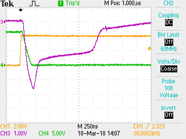
The B ramp also seem to have a portion of it's cycle in a fast damped oscillatory mode, coincident with the fast events seen for the A ramp:
Ringing detail with both ramps

Explanations as to the lack of symmetry in this circuit don't seem forthcoming. It would seem to make more sense for both ramps to have the same behavior exactly. From switch-only testing of the 2N7000, it was quite clear this little TO-92 MOSFET transistor can hold a tremendous amount of capacitive charge. The ringing then could be essentially an RLC oscillatory effect, with extra inductance inculcated from the CT capacitor (the yellow axial capacitor at left), which was inserted into the breadboard with flying leads:

However, what creates the B ramp pulse below ground is a mystery. A leading idea is that it's charge transfer between A and B cycles. But what's weird about that idea is that it's always the B ramp which has the anomalous pulse, no matter in what order things are when the circuit is first powered up.
These switching dynamics are leading credence to the idea that simpler means of generating precise square-waves for the mixer need to be found, to enable the idea of the Down-Conversion Frequency Synthesis. Perhaps as triangle-wave generation loop is a better solution, esp. since the current switched is symmetrical, and the waveform produced does not have fast edges. A Gilbert current mirror and diode-bridge switch could used to produce a very clean circuit. But even that seems like a lot of circuitry when the precision needed is over a small frequency span, 22-33 kHz.
Comments
Post a Comment