After 2 days of frustration wrestling with circuit design improvements for performance on my experimental Schmitt Trigger, I just had to go back to school. Amazing how much it takes to resolve what two transistors can do in tandem! I have found that Internet HowTo is generally lacking for this particular kind of circuit. A lot of subtle but important things are glossed over in hobbyist-oriented forums.
So, I hit the books, studying Millman & Taub, 2ed, 1968. Their explanation is analytical, and they provide a solid worked example. But while they offer analytical insight, they don’t really show you how to design a Schmitt Trigger, LOL. But having “designed” and tested several designs already, the analytical treatment in Millman & Taub was just the jump forward I needed. So, iterating my own design method, I got a first circuit that was clearly higher performance in every way. The main closure I needed was tuning resistor values to precisely set the upper trip-point, allowing the lower trip-point to fall where ever it might. This is OK, because the application is to sense the limit of a positive-rising sawtooth wave, and where the lower trip point falls during the fast retrace period is a non-issue. Related, +12V was used for Vcc, to allow a zener voltage reference against the main system positive rail of +15V -- this affords power-supply independent operation of thresholds in the Schmitt Trigger.
I see some anachronisms as well, between design thinking of 1968, and today. First, late-modern Silicon transistors like the 2N5088 offer much higher performance than generally available in the Sixties. In fact, the new circuit design works with triangle wave input to 100 kHz and beyond — without a speed-up capacitor that is de rigueur in the classic description of these circuits! Adding a capacitor did not speed up the circuit. It acts as a differentiator, increasing the amount of signal swing after fast switching events. This actually causes delays as the RC spike settles down, when the period is decreasing due to increasing frequency. Another thing is that the analytical view (per Millman & Taub) indicates what to expect only at the important inflection points in the operation of the circuit. But in actual fact, due to non-linear positive feedback, a lot of things happen between the key inflection points, depending on the input waveform. Typical analysis really does not cover this. Their treatment also indicated that a digital output can also take place at Q1 collector -- my observations bear otherwise. That is hardly a digital output, it's quasi-linear, highly dependent on the input signal. Similarly, the signal seen at the base of Q1 is quite different than that of the base at Q2. Depending on the input signal, the internal waveshapes seen are highly-complex.
Now, one good thing does come from this realization: the key points in the interior operation of a Schmitt Trigger definitely offer possibilities for wavefolding circuits for electronic music! Amazingly complex waveshapes emerge from the internal level-shifts caused by the positive feedback latching in a Schmitt Trigger. For now, let's take a look at the basic circuit, for its main purpose, now greatly improved:
Zoom to 100ns/div on rising edge output with 1 kHz triangle stimulus: fast circuit!
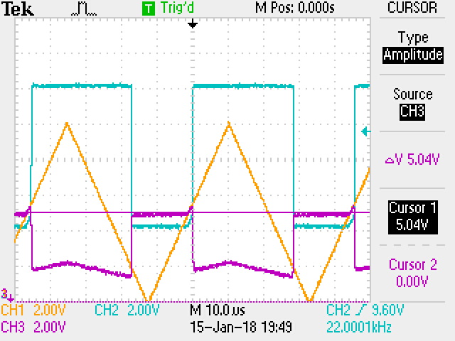
Operation at 22 kHz
And at 33 kHz
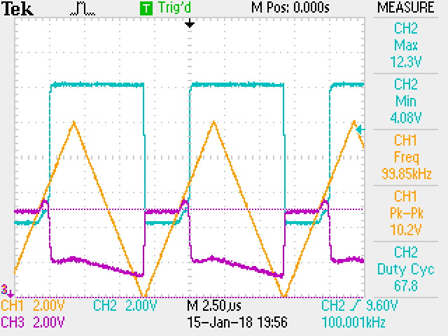
This Schmitt Trigger still works at 100 kHz
The common emitter voltage (VIO) at 50 kHz -- strange things with sawtooth input!
Pulse dynamics at 100 ns/div with 50 kHz signal
The common emitter falling-edge "anomaly" (VIO) at 33 kHz
Effect of 0.0022 µF speed-up capacitor on rising edge -- slows things down!
Effect of 0.0022 µF speed-up capacitor on falling edge -- mainly extra tilt.
Compared with common emitter (VIO), without a speed-up capacitor, and also showing 2µS "anomaly."
So, I hit the books, studying Millman & Taub, 2ed, 1968. Their explanation is analytical, and they provide a solid worked example. But while they offer analytical insight, they don’t really show you how to design a Schmitt Trigger, LOL. But having “designed” and tested several designs already, the analytical treatment in Millman & Taub was just the jump forward I needed. So, iterating my own design method, I got a first circuit that was clearly higher performance in every way. The main closure I needed was tuning resistor values to precisely set the upper trip-point, allowing the lower trip-point to fall where ever it might. This is OK, because the application is to sense the limit of a positive-rising sawtooth wave, and where the lower trip point falls during the fast retrace period is a non-issue. Related, +12V was used for Vcc, to allow a zener voltage reference against the main system positive rail of +15V -- this affords power-supply independent operation of thresholds in the Schmitt Trigger.
I see some anachronisms as well, between design thinking of 1968, and today. First, late-modern Silicon transistors like the 2N5088 offer much higher performance than generally available in the Sixties. In fact, the new circuit design works with triangle wave input to 100 kHz and beyond — without a speed-up capacitor that is de rigueur in the classic description of these circuits! Adding a capacitor did not speed up the circuit. It acts as a differentiator, increasing the amount of signal swing after fast switching events. This actually causes delays as the RC spike settles down, when the period is decreasing due to increasing frequency. Another thing is that the analytical view (per Millman & Taub) indicates what to expect only at the important inflection points in the operation of the circuit. But in actual fact, due to non-linear positive feedback, a lot of things happen between the key inflection points, depending on the input waveform. Typical analysis really does not cover this. Their treatment also indicated that a digital output can also take place at Q1 collector -- my observations bear otherwise. That is hardly a digital output, it's quasi-linear, highly dependent on the input signal. Similarly, the signal seen at the base of Q1 is quite different than that of the base at Q2. Depending on the input signal, the internal waveshapes seen are highly-complex.
Now, one good thing does come from this realization: the key points in the interior operation of a Schmitt Trigger definitely offer possibilities for wavefolding circuits for electronic music! Amazingly complex waveshapes emerge from the internal level-shifts caused by the positive feedback latching in a Schmitt Trigger. For now, let's take a look at the basic circuit, for its main purpose, now greatly improved:
Fast Precise Schmitt Trigger
Scope Fotos
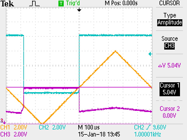
Correct operation for upper trip point of 5.0V.
Output in BLU, input in ORG.
(VIO) shows Q2b signal, which the input signal compares against.
Correct operation for upper trip point of 5.0V.
Output in BLU, input in ORG.
(VIO) shows Q2b signal, which the input signal compares against.
Zoom to 100ns/div on rising edge output with 1 kHz triangle stimulus: fast circuit!
And at 33 kHz
This Schmitt Trigger still works at 100 kHz
The common emitter voltage (VIO) at 50 kHz -- strange things with sawtooth input!
Pulse dynamics at 100 ns/div with 50 kHz signal
The common emitter falling-edge "anomaly" (VIO) at 33 kHz
Effect of 0.0022 µF speed-up capacitor on rising edge -- slows things down!
Effect of 0.0022 µF speed-up capacitor on falling edge -- mainly extra tilt.
Compared with common emitter (VIO), without a speed-up capacitor, and also showing 2µS "anomaly."
Homework, based on Millman & Taub


Comments
Post a Comment