This is a design took quite a lot of experimentation to get working correctly, and to acceptable performance levels. A circuit design completed in May was close to providing everything needed, but after further testing, limitations were revealed. For now, in this post, some quick background information, a cleaned up schematic, and quick development notes.
In synthesizers, there’s a general need for a voltage comparator. A comparator might be used in the control loop of a triangle or sawtooth core VCO, for pulse waveform conversion from other waveforms, for limit sensing in envelope followers, and in an envelope generator.
I’m specifically building with discrete transistors, and some kind of fast comparator was needed for the Model III EMS. In this context, fast here means relatively fast for audio, not fast as in ECL logic, or semiconductor tester types of speeds. So, one goal I had with this discrete design was to see how fast a voltage comparator could be made with bipolar analog switching outputs, so that it’s output could be used directly, in the service of an application circuit. Speed being of importance so as to reduce the proportion of time that might be dedicated to switching activity during the shortest periods of a waveform generator used at the high-end of the audio frequency range, and beyond.
I recreated the schematic from the working notes of the currently working circuit, as like before in May, iterations to the design were needed. So, before too much time passed on, seemed prudent to document the known working design. This is a first-prototype, the design may have some imperfections that need a little bit more work, such as some decoupling capacitors added. Also, as noted below, a more efficient form of the design is likely possible.

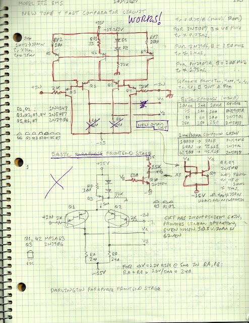
Also, one of the ideas that did not initially work was the use of a darlington transistor pair to provide superior current gain. A pair of 2N5087 transistors were ultimately used to improve the “snap” of the comparator. At first that did not work either. It now appears that the darlingtons may have been more viable than originally thought, when it was discovered later that using voltage readout output resistors instead of a current mirror greatly reduced the transconductance of the circuit. This idea will be revisited soon, because use of devices like MPSA63 would greatly reduce the component count, since two additional current references could be eliminated.
Here are the original working notes, and notations on early circuit measurements:
Here are the original working notes, and notations on early circuit measurements:


Comments
Post a Comment